Oscillator Simulation Example Using RINCON™.
By Gennady Serdyuk, <gserdyuk@gserdyuk.com>
Content
1. Itroiduction
2. Component Models
3. Frequency sweep simulation.
4. Oscillation simulation
5. Files
6. Conclusions
7. References
1. Introduction
This paper describes experience of oscillator simulation using Rincon VHDL-AMS/FD simulator [1].
Generally, Rincon have not implemented Oscillator Harmonic Balance yet, but Rincon’s Modulation Harmonic Balance solver may be used to simulate oscillators in time domain.
To demonstrate Rincon’s capability to simulate autonomous circuits, let us consider one-transistor oscillator, which uses phase-inverting resonance T-shape LC circuit. Schematic of this simulator is shown at fig. 1. Design of simulator is described in details in [2].
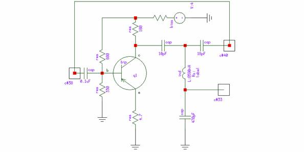
This oscillator is supposed to have oscillation frequency of 10MHz with output level around -5 dbm.
For purpose of simulation, let us pay attention to component models first. Then proposed circuit will be simulated in frequency sweep to look – does oscillation condition are possible. After that time –domain (using MHB solver) simulation will be performed.
2. Component Models
BJT is of type 2N2222. It’s parameters (according to [3] ) are the following:
.model m2n2222 npn is=19f bf=150 vaf=100 ikf=.18
+ ise=50p ne=2.5 br=7.5 var=6.4 ikr=12m
+ isc=8.7p nc=1.2 rb=50 re=0.4 rc=0.4 cje=26p
+ tf=0.5n cjc=11p tr=7n xtb=1.5 kf=0.032f af=1
Complete model of BJT is used here is presented below:
-- BIPOLAR SIMPLEST ---------------------
entity bjt is port (terminal e,b,c : electric); end entity;
-----------------------------------------------------
-- Gummel-Poon model.
------------------------------------------------------
architecture gp1 of bjt is
constant iss : real :=1.9e-15; -- transport saturation current
constant ise : real :=0; -- base-emitter leakage saturation current
constant isc : real :=0; -- base-collector leakage saturation current
constant vt : real := 0.0259; -- k Tj/q - thermal voltage
constant bf : real := 150; -- BF
constant br : real := 7.5; -- BR
constant nf : real := 1;
constant nr : real := 1;
constant ne : real := 2.5;
constant nc : real := 1.2;
quantity icoll through c;
quantity ibase through b;
quantity iem through e;
quantity vs1 across b to e;
quantity vs12 across b to c;
quantity vce across c to e;
begin
func: procedural is
variable ibf, ibr, ilc, ile: real;
variable kqb : real;
variable ice_r : real;
begin
kqb := 1;
ibf := iss* (myexp(vs1 /(nf*vt))-1);
ibr := iss* (myexp(vs12/(nr*vt))-1);
ile := ise* (myexp(vs1 /(ne*vt))-1);
ilc := isc* (myexp(vs12/(nc*vt))-1);
-- 1MEG between c and e to improve convergenece
ice_r := vce/1.e6;
-- all togeter.
icoll := ibf/kqb - ibr/kqb - ibr/br - ilc + ice_r;
ibase := ibf/bf + ibr/br + ilc + ile ;
iem := - icoll - ibase;
end procedural;
end architecture;
Models of other components:
Resistor (res):
-- res model
entity res is
Generic ( r: real );
Port ( terminal a : electrical;
terminal b : electrical );
end res;
architecture BEHAVIORAL of res is
quantity ur across ir through a to b;
begin
ir==ur/r;
end BEHAVIORAL;
Capacitor:
entity cap is
Generic ( c: real );
Port ( terminal a : electrical;
terminal b : electrical );
end cap;
architecture BEHAVIORAL of cap is -- this is common architecture
quantity u_cap across i_cap through a to b;
begin
i_cap==c*u_cap'dot+u_cap/1.e6;
end BEHAVIORAL;
architecture FREQ of cap is -- and this on uses FD attribute to
quantity u_cap across i_cap through a to b; -- define capacitor in frequency domain
begin
i_cap'FD==2.*math_pi*math_j*FREQUENCY()*u_cap'FD*c;
end;
It is worth to note, that both architectures are interchangeable for Harmonic Balance simulation but not for Modulation Harmonic Balance in current implementation. For MHB use ‘dot notation.
Inductor:
-- INDUCTOR --------------------------------------
entity ind is
generic (l: real);
port (terminal a, b: electrical);
end entity ind;
architecture BEHAVIORAL of ind is -- commonly used architecture
quantity u across i through a to b;
begin
u==l*i'dot;
end architecture;
architecture INTEG of ind is -- alternate implementation, uses ‘integ
quantity u across i through a to b; -- attribute
begin
i==1/l*u'integ;
end architecture;
architecture FREQ of ind is -- frequency-domain defined architecture
quantity u across i through a to b;
begin
u'FD==i'FD*2.*math_pi*math_j*FREQUENCY()*l;
end architecture;
architecture FREQ_INTEG of ind is -- again, but defines I=I(U,f)
quantity u across i through a to b;
begin
if (FREQUENCY() /= 0) use
i'FD==u'FD/(2.*math_pi*math_j*FREQUENCY()*l); -- usual i=u/ZL
else
u'FD==ZERO; -- if Zl ==0; -> UL == 0 too
end use;
end architecture;
DC source:
-- DC SOURCE TO GROUND ---------------------------------------
entity DCG is generic (E: real); port (terminal p: electrical);
end entity DCG;
architecture BEHAVIORAL of DCG is
quantity u across i_dc through p;
begin
u==E;
end architecture;
Note, that both “u” and “i_dc” quantities are declared, despite only “u” is used explicitly in equation. i_cd is used in implicit equations for ports “p” and “m”
Here is example for voltage source. It is not used directly in oscillator simulation, but is required to simulate frequency response of open loop.
entity source is
Generic ( V: real;
fr:real;
phase: real );
Port ( terminal a : electrical;
terminal b : electrical );
end source;
architecture BEHAVIORAL of source is -- frequency-domain defined voltage source
quantity u_source across i_source through a to b;
begin
if (FREQUENCY() = fr) use
u_source'FD==COMPLEX(0,V);
else
u_source'FD==ZERO;
end use;
end BEHAVIORAL;
architecture COSINE of source is -- same source shifted 90 degrees left (cosine)
quantity u_source across i_source through a to b;
begin
if (FREQUENCY() = fr) use
u_source'FD==COMPLEX(V,0);
else
u_source'FD==ZERO;
end use;
end COSINE;
architecture COS_RINT of source is -- cosine source with internal resistor
quantity u_source across i_source through a to b;
constant R_int : real := 0.1; -- internal resistance
begin
if (FREQUENCY() = fr) use
u_source'FD==COMPLEX(V,0)+i_source'FD*R_int;
else
u_source'FD==ZERO+i_source'FD*R_int;
end use;
end COS_RINT;
architecture COS_RINT1 of source is -- alternate implementation with r_int
quantity u_source across i_source through a to b;
constant R_int : real := 0.1;
begin
if (FREQUENCY() = fr) use
( u_source'FD - COMPLEX(V,0) ) / R_int == i_source'FD ;
else
u_source'FD/ R_int == i_source'FD;
end use;
end COS_RINT1;
All these alternate implementations are presented here to describe language constructs and flexibility.
At last – v_perturp. It is used to set up initial conditions for oscillator, as it may nave degraded solution with zero oscillation magnitude. It is shown, that this source changes it’s voltage passing from stationary initial point (QUESCENT_DOMAIN) to transient solution (TIME_DOMAIN).
entity v_perturb is
Generic ( V0: real); -- source voltage
Port ( terminal p : electrical;
terminal m : electrical );
end v_pulse;
architecture BEHAVIORAL of v_perturb is
quantity u_source across i_source through p to m;
begin
if (DOMAIN = QUIESCENT_DOMAIN) use
u_source == V0;
else --- DOMAIN==TIME_DOMAIN
u_source == 0;
end use;
end BEHAVIORAL;
All those models are stored in correspondent files in subdirectory “library”:
library/
res.vhdl
cap.vdhl
ind.vhdl
source.vhdl
DCG.vhdl
bjt.vhdl
3. Frequency sweep simulation.
To simulate frequency sweep, it is necessary to create circuit model for that:
-- vhdl-ams code for oscillator (open loop)
entity oscillator_ac is generic(f: real); end;
architecture schematic of oscillator_ac is
constant SpectrumShape: real :=1;
constant SourceFrequency1: real :=f;
constant SourceOrder1: real :=1;
terminal t1, t2, t3, t4, t5, t6, t7, t8, t101: electric;
begin
c4: entity cap(BEHAVIORAL) generic map (0.1e-6) port map (t1, t4);
r2: entity res(BEHAVIORAL) generic map (680) port map(t4,t5);
r1: entity res(BEHAVIORAL) generic map (330) port map(t4,ground);
r3: entity res(BEHAVIORAL) generic map (4.7) port map(t6,ground);
r4: entity res(BEHAVIORAL) generic map (180) port map(t5,t8);
q1: entity bjt(gp1) port map(t6, t4, t5);
c1: entity cap(BEHAVIORAL) generic map (10e-12) port map (t5, t7);
c2: entity cap(BEHAVIORAL) generic map (18e-12) port map (t7, t2);
c3: entity cap(BEHAVIORAL) generic map (470e-12) port map (t3, ground);
l1: entity ind(BEHAVIORAL) generic map (8590e-9) port map (t7,t3);
dc1: entity DCG(eq) generic map(4.0) port map(t8);
--Rloop: entity res(BEHAVIORAL) generic map (.1) port map(t2,t1);
--perturb: entity v_perturb(BEHAVIORAL) generic map (1) port map(t2,t1);
vin: entity source(COSINE) generic map (0.001,SourceFrequency1,0) port map(t101,ground);
rin: entity res(BEHAVIORAL) generic map (50) port map(t101,t1);
Rl2: entity res(BEHAVIORAL) generic map (50) port map(t2,ground);
Rl3: entity res(BEHAVIORAL) generic map (50) port map(t3,ground);
end;
and store in file osc-v-sweep.vhdl.
That code contains “f” in generic interface of entity. That means that frequency value may be passed there from outside. This frequency is used by “vin” voltage source. Amplitude of that source is set to 0.001 to be sure that signal is really small. Rincon does not contain small signal AC simulation, so large-signal simulation is used to compute quantities.
Program “rincon_p” is designed to use that feature. It is possible to write Python script, that can call simulator with different values of f_value.
Code of script is:
#---------------------------------------------------------------------
# use sweep object:
import math
print "FREQUENCY SWEEP ====================================================="
print ""
# sweep object has type SAFF (Sweep Ascii File Format):
sweep=SAFF() # create empty sweep data
sweep.names=["F1"] # assign names of sweep parameters. here list [] of one element - string "RL"
F0=0e6 # arrange loop
for i in range(10,90,10)+range(90,110,1)+range(110,200,10):
F=F0+100e3*i
res=HBparametric([F,1]) # parameters - F and number of harmonics
sweep.params.append([F])
sweep.hbblock.append(res)
# or access it to get data (similar to previous example):
print "F1 \t\t |k| \t\t < k \t\t"
for i in range(len(sweep.params)):
kv = sweep.hbblock[i].getX("t2'reference",[1])
ki = sweep.hbblock[i].getX("t1'reference",[1])
print sweep.params[i],"\t",\
abs(kv)/abs(ki), 10*math.log10(abs(kv)/abs(ki)),\
"\t", 180*math.atan2(kv.imag,kv.real)/3.14
Store that in file osc_v_sweep.jdl
Then compile osc_v_sweep.vhdl
$ rincon osc_v_sweep.vhdl
and run
$ rincon_p osc_v_sweep >osc_v_sweep.log
rincon_p script takes osc_v_sweep.jdl file and executes it.
It gives the following results:
F1 |k| |k| dB < k
[1000000.0] 0.000388428195 -34.106892524 42.278994343
[2000000.0] 0.002472929701 -26.067882293 61.7107871704
[3000000.0] 0.008276023498 -20.821782848 70.447669789
[4000000.0] 0.020803147939 -16.818709424 74.8349130865
[5000000.0] 0.044919639274 -13.475637399 77.0031140547
[6000000.0] 0.089437221844 -10.484816995 77.7481406535
[7000000.0] 0.172686643031 -7.6274125295 77.2651998815
[8000000.0] 0.340746475672 -4.6756862736 75.140560484
[9000000.0] 0.749014986769 -1.2550949257 69.1841404892
[9100000.0] 0.820169944969 -0.8609614942 68.1080556492
[9200000.0] 0.9009584793 -0.4529522303 66.8733515602
[9300000.0] 0.993195817685 -0.0296511791 65.4460855931
[9400000.0] 1.09910797203 0.41040357894 63.7813210195
[9500000.0] 1.22139490031 0.86856102354 61.8203212761
[9600000.0] 1.36329716814 1.34590532589 59.484857295
[9700000.0] 1.52857296689 1.84286174735 56.6694263332
[9800000.0] 1.7212769706 2.35850758257 53.2308210731
[9900000.0] 1.94507760879 2.88936934401 48.9745177776
[10000000.0] 2.20164063971 3.42746433198 43.6414833559
[10100000.0] 2.48733834517 3.95734865063 36.9049520691
[10200000.0] 2.78787671344 4.45273564313 28.4087288143
[10300000.0] 3.07242289871 4.8748099324 17.9085428925
[10400000.0] 3.29429243661 5.17762149165 5.56058061683
[10500000.0] 3.40712257563 5.32387758153 -7.79620252362
[10600000.0] 3.39226608359 5.30489910242 -20.8130805048
[10700000.0] 3.27034161908 5.14593121325 -32.3249871128
[10800000.0] 3.08412099249 4.89131407427 -41.8426748461
[10900000.0] 2.87390972179 4.58473121508 -49.448444817
[11000000.0] 2.66608862878 4.25874582568 -55.4679169795
[12000000.0] 1.50687728647 1.78077886702 -78.9564392199
[13000000.0] 1.1470713816 0.59590444639 -85.0641991481
[14000000.0] 0.995312019236 -0.0204075142 -87.8709829747
[15000000.0] 0.920958214468 -0.3576007407 -89.5387737547
[16000000.0] 0.883338464885 -0.5387285784 -90.6886267254
[17000000.0] 0.865953309456 -0.6250552367 -91.5624525177
[18000000.0] 0.860880515524 -0.6505712154 -92.2729823502
[19000000.0] 0.863838411603 -0.6356748843 -92.8794017439
It is similar to data published in [2](Fig 7).
To compare – here is SPICE AC result
4. Oscillation simulation
VHDL-AMS code was slightly changed to perform oscillation simulation.
-- vhdl-ams code for oscillator
entity oscillator is end;
architecture schematic of oscillator is
constant SpectrumShape: real :=0;
terminal t2, t3, t4, t5, t6, t7, t8: electric;
begin
-- c4: entity cap(BEHAVIORAL) generic map (0.1e-6) port map (t1, t4);
r2: entity res(BEHAVIORAL) generic map (680) port map(t4,t5);
r1: entity res(BEHAVIORAL) generic map (330) port map(t4,ground);
r3: entity res(BEHAVIORAL) generic map (4.7) port map(t6,ground);
r4: entity res(BEHAVIORAL) generic map (180) port map(t5,t8);
q1: entity bjt(gp1) port map(t6, t4, t5);
c1: entity cap(BEHAVIORAL) generic map (10e-12) port map (t5, t7);
c2: entity cap(BEHAVIORAL) generic map (18e-12) port map (t7, t2);
c3: entity cap(BEHAVIORAL) generic map (470e-12) port map (t3, ground);
l1: entity ind(BEHAVIORAL) generic map (8590e-9) port map (t7,t3);
dc1: entity DCG(eq) generic map(4.0) port map(t8);
Rloop: entity res(BEHAVIORAL) generic map (0.1) port map(t2,t4);
perturb: entity v_perturb(BEHAVIORAL) generic map (1) port map(t2,t4);
Rload: entity res(BEHAVIORAL) generic map (50) port map(t3,ground);
end;
Here are some point deserve to be explained.
Rloop – resistor to connect output of cascade (t2) with input (t4).
C4 was present in open loop simulation, here it is removed.
Perturb voltage source is used to set initial value to “kick” oscillator.
Assume that it is stored in osc-v1.vhdl file. To run simulation – compile and simulate
$ rincon osc-v1.vhdl
$ hbsim osc-v1 --mhb --mhb --time 2.e-6 1.e-9 --mhbdt c --mhbf osc-v1.icd
Results are:
Output voltage (t3’reference) 120 mV, frequency about 10.25MHz
It is important to keep small steep of integration – Backward Euler formula is used currently and it is sensitive to step size. Present results are obtained with step 1.e-9 sec = 1 ns, i.e. 100 points over period. Less step size may show other behavior, for example decaying of oscillations.
Similar behavior show other simulation programs, for example Dolphin’s SMASH simulator, if used with Backward Euler integration formula.
Same circuit was simulated using SPICE-based simulator. Here are circuit netlist and output voltages:
Calculated values: Frequency = 10.28Meg, Vout=150mV
These results are obtained using trapezoidal integration formula.
Backward Euler formula have much less precision and solution shape is dependent on integration step. It does not converge to periodic solution with step more than 1.e-9 sec and gives correct solution at step of 1.e-10 sec and less.
5. Files
All files are gathered in rincon-oscillator1.zip archive. Content is:
./rincon: - rincon files
library - library of elements
DCG.vhdl
bjt.vhdl
cap.vhdl
ind.vhdl
res.vhdl
source.vhdl
v_perturb.vhdl
osc-v-sweep.bat - WIN bat file to start sweep
osc-v-sweep.jdl - JDL file for sweep
osc-v-sweep.vhdl - VHDL file for SWEEP
osc-v1.bat - bat file to run socillator simulation
osc-v1.vhdl - model for oscillator
./smash:
oscillator1-ac.cir - spice file for AC simjulation
oscillator1.cir - spice for TRAN simulation
6. Conclusions
This report shows how to use Rincon VHDL-AMS/FD simulator to simulate oscillators in time domain - how to simulate open loop cascade, set up initial condition to start oscillator simulations. Shown how to run simulator in different modes – HB and MHB (Harmonic Balance and Modulated Harmonic Balance).
It is noted, that used Backward Euler formula creates some limitation to time-domain simulation, requiring small step size.
References
[1] Rincon VHDL-AMS/ FD Simulator http://www.ridgetop-group.com
[2] R. Rhea, A New Class of Oscillators, IEEE Microwave Magazine, Vol. 5, No. 2, June 2004, pp. 72 – 83.
[3] All About Circuits. http://www.allaboutcircuits.com/vol_5/chpt_7/4.html
Rincon ™ is trade mark of Ridgetop Group, Inc. Other used trade marks are property of their respective owners.